
Earth resistance test companies in Bangladesh measure how easily fault current can flow from an earthing system into the ground. TOTO POWER Engineering tests the earth pits and electrodes at factories and buildings, records the readings for each pit, and recommends improvements wherever the resistance is too high for safe electrical and lightning protection.
Last updated: 7 October 2026
Among earth resistance test companies in Bangladesh, TOTO Power Engineering tests earthing systems for factories, large industrial facilities, commercial buildings and power installations. We measure every earth pit, explain what the results mean and recommend practical repairs, as part of our wider testing and inspection services.
Earthing (grounding) is what keeps electrical equipment safe when something goes wrong. Regulators, buyers and insurers around the world expect electrical installations to be properly earthed, and several tests are used to prove it. The earth resistance test is one of the most important, because it shows whether fault current and lightning current can actually flow safely into the ground.
Class I equipment, such as metal-cased motors, grinders, panels and many hand tools, relies on a protective earth conductor. If that conductor or the earth electrode fails, the metal casing can become live during a fault, and the consequences can be fatal.
Earth resistance should be measured to confirm the integrity of the electrical system. An earth electrode that performed well when it was installed does not stay that way: soil dries out, groundwater levels fall and buried rods and joints corrode. Poor earthing increases the likelihood of equipment failure and is dangerous for people, especially during thunderstorms or utility overvoltages. That is why earthing systems should be tested at installation and then periodically throughout their life. When a reading has risen significantly compared with earlier results, our technicians investigate the cause and recommend changes to bring the resistance back down.
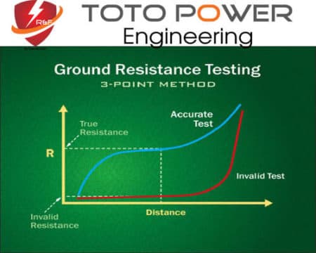
An earth resistance test measures the resistance, in ohms, between an earth electrode (or a complete earthing system) and the general mass of the earth. The lower and more stable this resistance, the more easily fault current can flow, so that fuses and circuit breakers operate quickly and touch voltages stay low. The test is carried out with a dedicated earth tester, not an ordinary multimeter, because it must inject a test current through the soil and reject stray voltages that are always present in the ground.
We follow the fall-of-potential (three-point) method described in IEEE 81, which is the reference method for measuring the resistance of a single electrode or a small earthing system:
Impact of rod length: Driving a rod deeper usually lowers its resistance, because it reaches more stable, moister soil. The improvement is significant but not proportional, so doubling the length does not halve the resistance.
Multiple rods: Two or more rods connected together create parallel paths to earth. The combined resistance is lower than that of one rod, but only if the rods are spaced far enough apart; rods placed too close together share the same soil and give much less benefit.
Soil treatment: Where deep rods cannot be driven, for example because of rock or a high-resistivity layer, the soil around the electrode can be improved with earth-enhancement backfill such as bentonite or conductive concrete. Salt-based treatments work but can corrode the electrode, damage nearby concrete and wash away over time, so they need care and should respect local environmental rules.
Soil resistivity is driven mainly by moisture and dissolved salts, and to a lesser extent by temperature.
Earthing is easy to forget because it is buried. We recommend that earth electrodes and their connections are checked as part of regular preventive maintenance, and that each new reading is compared with the previous ones.
If a reading has risen noticeably since the last test, the technician should find the cause and correct it, usually by repairing connections, replacing a corroded electrode or adding a rod to the system.
The cost depends on the work involved rather than a fixed rate. The main factors are:
Contact us with the number of pits and your site location for a quotation.
IEEE 81 is the main guide for measuring earth resistance and soil resistivity. The design of the earthing itself follows the requirements of BNBC 2020 and IEC 60364 for low-voltage installations, and IEC 62305 where the earth electrode is part of a lightning protection system. For factories, earthing records are also reviewed during DIFE inspections and buyer electrical safety audits.
Earthing is closely linked to lightning protection and overall electrical safety. See our lightning protection system service, our electrical safety assessment and the cable insulation resistance test.
They measure the resistance between each earth electrode, or the whole earthing system, and the surrounding soil. A typical job covers the earth pits for the transformer and generator neutral, the main distribution boards, the lightning protection system and sensitive equipment. The report lists every pit, its measured value, the test method and recommendations for any pit that needs improvement.
The most common method is the fall-of-potential (three-point) method described in IEEE 81. Two auxiliary stakes are driven into the ground in a straight line from the electrode under test, current is injected and the voltage is measured at several distances. Where the electrode cannot be disconnected, a clamp-on tester can be used, with its limitations explained in the report.
Earthing should be tested when it is installed, after any modification and then periodically as part of your maintenance plan, as well as before compliance audits. Testing in the dry season is useful because soil is driest and resistance is highest then. Comparing each new reading with earlier results shows whether an electrode is corroding or the soil is drying out.
There is no single value for every installation. The acceptable figure depends on the type of system, the protective devices used, the fault current, the lightning protection design and the requirements of the designer, the utility or the buyer. We compare each reading with the value specified for your installation and explain clearly which pits pass, which fail and why.
First we check connections, the test set-up and the condition of the electrode, because a loose or corroded joint is a common cause. If the electrode itself is inadequate, options include driving a longer rod, adding rods spaced well apart, improving the backfill around the electrode or building a new pit. We then re-test to confirm the improvement.
Yes. Earth resistance testing is a core part of an electrical safety assessment, alongside thermography, insulation resistance testing and a visual inspection of panels and cables. Poor earthing can stop protective devices from operating during a fault and can make lightning protection ineffective, so assessors and buyers routinely ask to see recent earth resistance test results.
